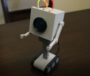
I was inspired by a Thingiverse model that a friend of myn had asked me to print for him. I wanted to make my own version, but with a few electronics added. I had a long list of goals in mind, however I only managed to achieve a few of them.
- Speak its lines
- Blink LED, like in its scene
- Moving Arms
- To slouch over and sit up straight
- Microphone to react to noise
- Moving track system so it could move around
- Camera to identify things in its view (like turn to a person)
- Battery powered
- Search out for its own base station to recharge
I didn’t achieve all of these things, in fact after I figured out what I felt was the bare minimum (bold in the list above) I kind of drew the line there. Essentially I tried to make my robot as closely as possible to scale. This is my first time ever doing anything like this, the only experience I had coming into this project is my familiarity with Arduino.
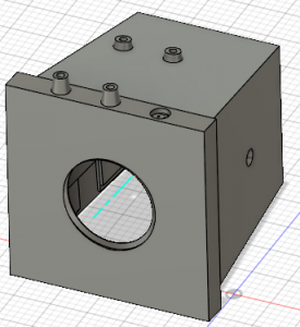
I’ve never tried to replicate something from tv show/movie before so trying to figure this out is first. I started by googling the average size of a brick of butter as the robot is shown beside a brick of butter. I never really found a consistent answer, 3x3x8 inches seemed to be the most common answer. The bricks of butter I buy (Gay Lea) are about 2.7×2.7×5 inches here in Ontario. In the TV show the brick of butter looked quite elongated so I felt the 3x3x8 was the correct size to scale thing to. So I printed off a few frames showing the robot and brick of butter to find my scale, then took measurements using my trusty master craft caliper. Using these measurements I created my model in Fusion 360 (startup license).
Required Tools & Supplies
- Soldering Iron & Solder
- Wire Cutters
- 18 AWG yellow silicone wire (3-4″)
- 18 AWG red silicone wire (3-4″)
- 24 AWG wire, not entirely necessary, nut nice it have
- Wire wrap wire, multiple colours will make it easier to wire
- Screw drive for your chosen screws
- 4-40 machine pan/button head 1/4″ screws (3x)
- 4-40 machine undercut flush head 1/4″ screws (5x), not entirely needed, the pieces these fasteners are used to secure; fit together pretty nicely without them
- CUI CMS-28588N-L152 Speaker
- Arduino Pro Mini (5v or 3.3v model, I used a 3.3v model)
- FTDI USB TTL Converter (for programming an Arduino Pro Mini)
- 2″x1″ piece of perf board
- 1K Ohm through hole resistor (3x)
- 2N2222A Transistor
- Adafruit 1833 – Micro USB Breakout
- FT90M Micro Servo (robotshop.com)
- HS-40 Nano Servo (robotshop.com)
- 5mm Red LED
- Tactile Button 1-1825910-4
- 2×3 (6 Pin) right angle, 2.54mm spacing male connector
- 3pin JST connector male
- 3pin JST connector female
- 2pin JST connector male (2x)
- 2pin JST connector female (2x)
- JST female tips for the connectors (7x)
note: the JST connectors aren’t essential, but are convenient for disconnecting power/push button, speaker and LED - Super glue, I prefer Gorilla brand super glue
- Assort small clamps
- 3D printer (I used a FlashForge Finder)
- Black filament
- White/Grey filament (these pieces will just be spray painted
- Light Grey Primer in a spray can
- Dark Grey Primer in a spray can
I think this is everything anyways
The 3D parts that will need printing
| Part | Comment |
 |
Paint/Prime light grey, 10 hour print, 64 grams of material. Light Grey |
| Completed list coming soon |
Files and Documention
