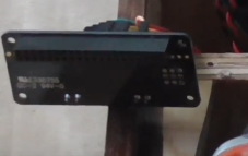
At the beginning of the video I build a controller board using an Arduino Pro Mini (clone), 6x tact buttons, 6x 10k resistors, 10k pot, perf board and some wire. The Arduino code is in the zip file below along with a PDF of the schematic. This communication board talks to the Raspberry Pi via TTL level UART. The Raspberry Pi runs a program listening on the UART interface for the commands and then repeats them to MPD.
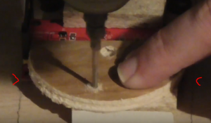
Once the board is completed I secure it to the front of the unit using some imperial 4 wood screws (4:10).
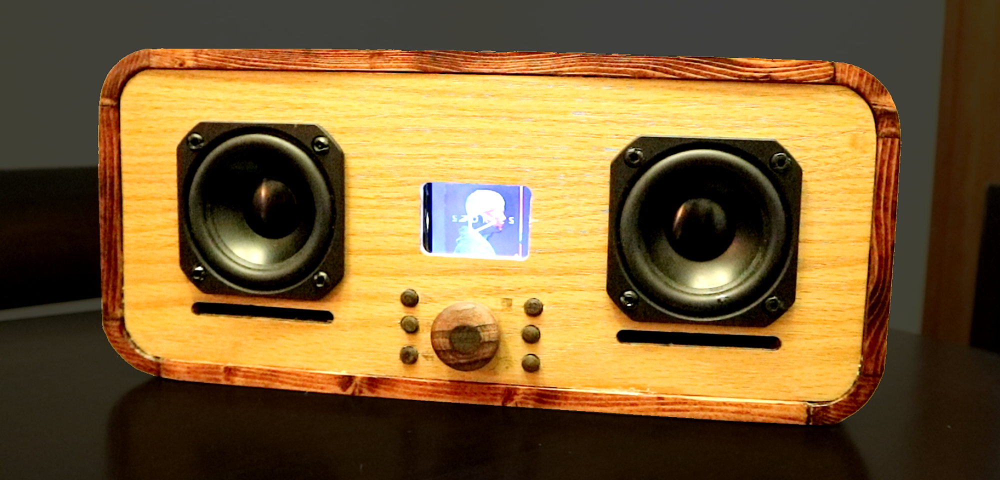
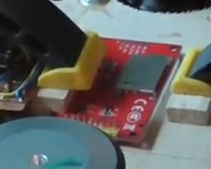
The display (4:45) I used in my build I purchased from sain smart (link below), but you can use any small SPI display that works with fbtft and it small enough to fit in the space. Although that 2.2″ module uses up almost all of the width available, as seen in the video (6:30).
I use female to female jumper cables to connect the controller board and the display to the Raspberry Pi allowing for a greater degree of serviceability…. if only i had smaller hands.
The Raspberry Pi HAT that I used, that can be purchased from Adafruit for $13US is the whole reason why I did this project in the first place was due to how scarce the Pi Zero W was after it release in 2017. The cheapest way to get a Pi Zero W was to buy it with this HAT, so logically I had to build something to make use of this HAT with a Raspberry Pi 3 and thus the BoomBox project began!
wifi_speaker_controller_Pi sketchup for arduino
2.2" Serial Port TFT SPI LCD Screen Module
https://www.adafruit.com/product/3346
https://www.adafruit.com/product/2377