Pass The Butter Robot (Rick and Morty robot) – Part 1


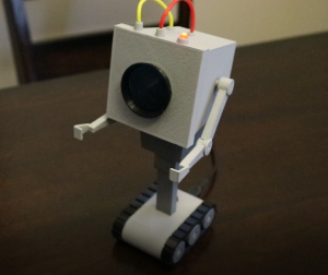
I was inspired by a Thingiverse model that a friend of myn had asked me to print for him.  I wanted to make my own version, but with a few electronics added.  I had a long list of goals in mind, however I only managed to achieve a few of them.

  • Speak its lines
  • Blink LED, like in its scene
  • Moving Arms
  • To slouch over and sit up straight
  • Microphone to react to noise
  • Moving track system so it could move around
  • Camera to identify things in its view (like turn to a person)
  • Battery powered
  • Search out for its own base station to recharge

I didn’t achieve all of these things, in fact after I figured out what I felt was the bare minimum (bold in the list above) I kind of drew the line there.  Essentially I tried to make my robot as closely as possible to scale.  This is my first time ever doing anything like this, the only experience I had coming into this project is my familiarity with Arduino.

I’ve never tried to replicate something from tv show/movie before so trying to figure this out is first.  I started by googling the average size of a brick of butter as the robot is shown beside a brick of butter.  I never really found a consistent answer, 3x3x8 inches seemed to be the most common answer.  The bricks of butter I buy (Gay Lea) are about 2.7×2.7×5 inches here in Ontario.  In the TV show the brick of butter looked quite elongated so I felt the 3x3x8 was the correct size to scale thing to.  So I printed off a few frames showing the robot and brick of butter to find my scale, then took measurements using my trusty master craft caliper.  Using these measurements I created my model in Fusion 360 (startup license).

Required Tools & Supplies

  • Soldering Iron & Solder
  • Wire Cutters
  • 18 AWG yellow silicone wire (3-4″)
  • 18 AWG red silicone wire (3-4″)
  • 24 AWG wire, not entirely necessary, nut nice it have
  • Wire wrap wire, multiple colours will make it easier to wire
  • Screw drive for your chosen screws
  • 4-40 machine pan/button head 1/4″ screws (3x)
  • 4-40 machine undercut flush head 1/4″ screws (5x), not entirely needed, the pieces these fasteners are used to secure; fit together pretty nicely without them
  • CUI CMS-28588N-L152 Speaker
  • Arduino Pro Mini (5v or 3.3v model, I used a 3.3v model)
  • FTDI USB TTL Converter (for programming an Arduino Pro Mini)
  • 2″x1″ piece of perf board
  • 1K Ohm through hole resistor (3x)
  • 2N2222A Transistor
  • Adafruit 1833 – Micro USB Breakout
  • FT90M Micro Servo (robotshop.com)
  • HS-40 Nano Servo (robotshop.com)
  • 5mm Red LED
  • Tactile Button 1-1825910-4
  • 2×3 (6 Pin) right angle, 2.54mm spacing male connector
  • 3pin JST connector male
  • 3pin JST connector female
  • 2pin JST connector male (2x)
  • 2pin JST connector female (2x)
  • JST female tips for the connectors (7x)
    note: the JST connectors aren’t essential, but are convenient for disconnecting power/push button, speaker and LED
  • Super glue, I prefer Gorilla brand super glue
  • Assort small clamps
  • 3D printer (I used a FlashForge Finder)
  • Black filament
  • White/Grey filament (these pieces will just be spray painted
  • Light Grey Primer in a spray can
  • Dark Grey Primer in a spray can

I think this is everything anyways

The 3D parts that will need printing


Part Comment
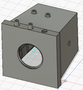
Paint/Prime light grey, 10 hour print, 64 grams of material. Light Grey
Completed list coming soon


Files and Documention

3D Files Complete

Arduino Program v1

Electronic Schematic


BoomBox Part 3

At the beginning of the video I build a controller board using an Arduino Pro Mini (clone), 6x tact buttons, 6x 10k resistors, 10k pot, perf board and some wire.  The Arduino code is in the zip file below along with a PDF of the schematic.  This communication board talks to the Raspberry Pi via TTL level UART.  The Raspberry Pi runs a program listening on the UART interface for the commands and then repeats them to MPD.

Once the board is completed I secure it to the front of the unit using some imperial 4 wood screws (4:10).

The display (4:45) I used in my build I purchased from sain smart (link below), but you can use any small SPI display that works with fbtft and it small enough to fit in the space.  Although that 2.2″ module uses up almost all of the width available, as seen in the  video (6:30).

I use female to female jumper cables to connect the controller board and the display to the Raspberry Pi allowing for a greater degree of serviceability…. if only i had smaller hands.

The Raspberry Pi HAT that I used, that can be purchased from Adafruit for $13US is the whole reason why I did this project in the first place was due to how scarce the Pi Zero W was after it release in 2017.  The cheapest way to get a Pi Zero W was to buy it with this HAT, so logically I had to build something to make use of this HAT with a Raspberry Pi 3 and thus the BoomBox project began!


wifi_speaker_controller_Pi sketchup for arduino

arduino controller schematic

2.2" Serial Port TFT SPI LCD Screen Module

https://www.adafruit.com/product/3346

https://www.adafruit.com/product/2377

PLS75F25AL0208

BoomBox Part 2

After cutting the pieces for the front and back (shown in part 1), I use acetone (0:55) to transfer the toner from the paper to my material.  Remember to print you page mirrored and to use a laser printer.  The documents used are attached at the bottom of this post and are also symmetrical so there isn’t any reason to print them mirrored.

Using a wood nail as a sudo punch (1:05) I mark where i need to drill holes.

(5:05) This is why this channel is called Inappropriate_tools, I placed some 1/4″ dowel into the chuck of my drill press and used a combination of sand paper (80 and 220 grit), metal file and a wood jigsaw bit to make my buttons.  Later I use a similar technique to make the volume knob.  First I need to make a jig (6:45) to attach the larger 1″ doweling to.

BoomBox Back

BoomBox Front

BoomBox Part 1


In part 1 of my video I show how to build the frame that everything will attach to and how I “skinned” it using a cut down 2×4.  Tools used in the project include drill press, table saw and a band saw.

The corner pieces I start with a small piece of 2×4 and used a 1 1/2″ (38mm) hole saw bit and then followed up with 2 1/2″ (64mm) how saw bit as shown in the video (1:32).  I repeated this for a total of three pieces which you then see me glue together.  The three cylinder cut pieces are then sanded using a drum sander bit meant for a pneumatic tool, but I just used my drill press, because Inappropriate_tools, that’s why!  I like to use gorilla glue, I’ve found when properly used this glue keeps pieces stuck together.  You do need to clamp pieces together as gorilla glue expands as it dries and this is what makes it so good.  It’ll expand in every crevice it can fit itself into, making it quite useless when gluing smooth surface objects.

Next I use my table saw to rip some 2×4’s (2:35) in about 4′ length, 3 pieces which I’ll glue together as shown and you a table top router to make them even and flat.  Alternatively you can find hobby size pieces of pine about the size you need at Home Depot or other DIY type stores (some to lots of sanding might be required)

Once the glue was set on my corner pieces I used my band saw to cut the one piece into quarters.  First by cutting it in half and the cutting the two half pieces in a half again.  After doing this twice I feel as you the table saw with 120-140 tooth blade might be a better way to go.  When I build the third one (bluetooth/fm radio) unit I think i’ll use the table saw instead for this part.

Next I begin work on the “skeleton” of the build (3:35), essentially a plywood structure that will provide plenty of support and structure.  One of my friends commented how he felt he could crush my creation, I took the back off and he quickly changed his mind.  I also cut the material that I will use for the front and back of the build, but these pieces won’t be covered until parts 2 and 3 of the project.  Below should be a PDF containing a 1:1 scale of the drawing shown in the video (3:56).  More drawings will be posted in Parts 2 & 3.  These initial 4 pieces cut from plywood will form the outer pieces and as such will have rounded corners.  I’ll use my cut corner pieces (4:15) to transfer the profile of the corner to the plywood before using my band saw to to cut them out.

Cutting these pieces was pretty difficult, the video is running at 20x and a skip a part where I had to stop and walk away for a minute.

Once the outer sections are cut and I need to cut pieces (4:55) for the “center” H section that will join everything together.  These piece will be glued (normal wood glue) and screwed and I’m using normal wood glue because its being secured with screws and I’ll secure the outer “skin” pieces to it using gorilla glue.  This will be super wicked solid when its done.

With the skeleton assembled I turn my attention back to the 2×4 that I cut down earlier.  With the three pieces glued together I need to plain them down to the correct thickness and make them flat.  Again you should be able to find hobby/diy pieces close enough.

Now that the the ripped 2×4 are planed down I have everything needed to “skin” the sides, top and bottom to the “skeleton” of the BoomBox.  I use hot glue (6:40) as a sorted of temporary way of securing pieces to figure out how things can fit together.  Basically we are at the super tedious part of the build where everything goes together and being that we are working with wood that means lots of cutting, sanding and adjusting.  The thing about wood is it can warp after its been cut, even wood that’s been sitting for a year plus (granted much less likely) and I’m using 2×4 that I just bought, so it super finicky.

To fill the gaps I squeeze in some wood glue and start sanding.  As I sand I push the left over saw dust into the wood glue and eventually fill the gap.  You need to sand the material regardless or you’ll end up with a rough surface and the stain won’t look very nice at all, so its win win.

In the video I don’t really show the beginning of the stain process, I accidentally filled up the sd card and hadn’t realized it.  Staining is pretty simple, just read the instructions on the container and you’ll end up with good results.  Darker stains are easier to apply as my experience has been they can only get so dark.

BoomBox Sheet3